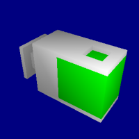
Intelligent Reuse of CAD Models and Manufacturing Plans


Project Description

In this research a fully automated and reconfigurable hybrid process planner that intelligently reuses and adapts old process plans to fit to new parts has been proposed and implemented. Plan reuse is made possible by first extracting features and blocks, and using the information of features and their interactions to find similar parts. A database indexing scheme is developed based on the feature interaction graph which quickly prunes unwanted parts, thus speeding up the process of similarity matching. Similarity of a part is determined by evaluating the distance between the feature interaction graphs of old and new part. The most similar part is one that has the most similar topology and manufacturing processes for each block of the new part. Each of the old block that is most similar to the new block is reused and modified to fit to the new part. If an old process plan is unavailable then a new plan is generated from scratch using generative process planning approach. All the processes are completely automated and the system works without any human intervention from start to finish.

There are several sub tasks and algorithms involved in this research which can be replaced by pluging in new algorithms and methods. Hence this system is extensible. The areas where plugins are allowed include feature recognition, database indexing scheme, matching blocks, block relaxation, modifying plan, generative process planning and plan merging. In addition to the plug-in capability of the system, there are several parameters that can be modified by the user to suit his needs. These parameters include relaxation costs between features, relaxation costs between interactions, number of relaxation in feature recognition, number of relaxations in database indexing and graph matching and tolerance of reusing process parameters.


Query Part

Similar Part
Fig 1. Retrieve a Similar part (right) for the Query model (left) from the database of already manufactured parts


		Setup: <y, x>
		Select tool: 8
		Do operation: End Mill slot 235
		Select tool: 9
		Do operation: End Mill blind-slot 63
		Select tool: 4
		Do operation: Fine End Mill blind-slot 63
		Select tool: 17
		Do operation: Drill pocket 44
		Select tool: 7
		Do operation: End Mill pocket 44
		Select tool: 16
		Do operation: Drill hole 49
		Do operation: Drill hole 50
		Select tool: 6
		Do operation: End Mill hole 49
		Do operation: End Mill hole 50
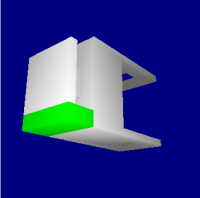
		Setup: <y, -z>
		Select tool: 15
		Do operation: End Mill slot 212
		Select tool: 16
		Do operation: Drill hole 47
		Do operation: Drill hole 48
		Select tool: 6
		Do operation: End Mill hole 47
		Do operation: End Mill hole 48
		Select tool: 1
		Do operation: Fine End Mill hole 47
		Do operation: Fine End Mill hole 48
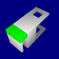
		Setup: <x, y>
		Select tool: 8
		Do operation: End Mill slot 213
		Do operation: End Mill slot 239
		Setup: <x, -y>
		Select tool: 16
		Do operation: Drill hole 45
		Do operation: Drill hole 46
		Select tool: 6
		Do operation: End Mill hole 45
		Do operation: End Mill hole 46
		Setup: <z, -x>
		Select tool: 15
		Do operation: End Mill step 306
		Setup: <z, x>
		Select tool: 15
		Do operation: End Mill step 313
	
		Setup: <x, y>
		Select tool: 16
		Do operation: Drill pocket 21
		Select tool: 17
		Do operation: Drill pocket 19
		Select tool: 8
		Do operation: End Mill slot 272
		Do operation: End Mill slot 271
		Select tool: 6
		Do operation: End Mill pocket 21
		Select tool: 7
		Do operation: End Mill pocket 19
		Select tool: 16
		Do operation: Drill hole 74
		Do operation: Drill hole 75
		Select tool: 6
		Do operation: End Mill hole 74
		Do operation: End Mill hole 75
		Setup: <y, z>
		Select tool: 8
		Do operation: End Mill slot 264
		Select tool: 9
		Do operation: End Mill blind-slot 92
		Select tool: 4
		Do operation: Fine End Mill blind-slot 92
		Select tool: 17
		Do operation: Drill pocket 73
		Select tool: 7
		Do operation: End Mill pocket 73
		Select tool: 16
		Do operation: Drill hole 78
		Do operation: Drill hole 79
		Select tool: 6
		Do operation: End Mill hole 78
		Do operation: End Mill hole 79
		Select tool: 1
		Do operation: Fine End Mill hole 79
		Setup: <y, -z>
		Select tool: 15
		Do operation: End Mill slot 245
		Select tool: 16
		Do operation: Drill hole 76
		Do operation: Drill hole 77
		Select tool: 6
		Do operation: End Mill hole 76
		Do operation: End Mill hole 77
		Setup: <z, -x>
		Select tool: 15
		Do operation: End Mill step 339
		Select tool: 5
		Do operation: Fine End Mill step 339
		Setup: <z, x>
		Select tool: 15
		Do operation: End Mill step 349
	
Fig 2. Reuse old process plan (left) and modify it to fit to the new part (right)


System Overview

Fig. 3 shows the system framework. The blocks in the figure are parts of the system that can be modified by the user. All the components together make a complete automated system that can reuse old plans and modify them to fit to new parts. The arrows show the direction which the system takes after performing a task corresponding to the component.


Fig 3. System Framework


After reading the BRep file of the new part and its delta volume the system proceeds to generate predicate file for the new part. The predicate file is an intermediate data that is required by the feature recognition algorithm (see [1]). The predicate file consists of information about each face type of the new part and the relation between various faces. A predicate file looks as follows (some information has been truncated)
f r
f r
f b
f r
f r
:

X 16 17
A 16 17
P 16 17
X 15 17
A 15 17
P 15 17
O 15 16
X 14 17
A 14 17
:

0 6 9
0 6 8
0 8 11
0 9 11
:
The predicates file consists of 3 sections. The first section consists of information regarding the face type. The "r" following an "f" indicates that the face is real, similarly a border face is represented by "b". The second section consists of the relation between two faces. An "X" represents that the two faces following the symbol make a convex angle. Other symbols include A, P, O, C for adjacent, Perpendicular, Opposite, Concave. The third section consists of each vertex in the object defined by the intersection of the three planes formed by the three faces. In the above example the planes in which the faces 0, 6 and 9 lie intersect to generate a vertex and so on.

The Feature Extractor uses this predicates file to extract all the features from the part using the method proposed in [1]. To avoid the problem of multiple interpretations of the same features, all non-maximal features are removed. Fig 4 shows all the maximal features (in green) found for a part.


Fig 4. Maximal features of an example part


The block handler combines interactiong features into blocks. For the above example part there are two blocks as shown in Fig 5.


Fig 5. Blocks for the example part


Block Retriever generates an index into the database using the features and their interactions for each block and retrieves a set of candidate similar blocks from the database. A feature interaction graph is developed for both the new part and the part to be matched using spatial relationships (see [2]). These old blocks are then matched with the block of the new part and ranked according to the similarity. The rank is based on the distance measure between the feature interaction graphs for the old block and the new block. Fig 6. shows the similar parts retrived query part.


Fig 6. Query part (left) and a similar part (right)


Finally the process plan of the similar part is retrieved from the database and modified to fit to the new part. If an old part cannot be retrieved from the database then a plan is generated from scratch. The following slides shows how process plan is reused. The left side show process plan of the new part and the right side shows the process plan of the old similar part.


From the following slide it can be observed that the hardness for both parts is similar. Also the features are similar, although a feature in the new part (feature 16) does not have a corresponding similar feature in the old part. Hence we know that some of the old process plan can be reused while some of the plan has to be generated. One such generated process operation is Pr1 which is the process operation for feature 16 that is missing in the old plan.


The next slide shows that some of the end tolerances and side tolerances are similar between the new and old parts (indicated by green characters), while some of the tolerances are much finer in the old process plan (indicated by blue) and some tolerances are much lower in the old process plan when compared to the new process plan (indicated by red). Hence the complete old process plan cannot be reused in the new process plan. Some of the old process plan such as Pr1, Pr2, Pr3 are reused. However Pr4 in the old plan is not reused because the finishing operation is not necessary in the new part as the tolerance requirement of feature 15 of the new part is not as low as the tolerance of feature 6 in the old part.


A new finishing operation is generated (show in red below), for feature 14 since the new part's tolerance for that is feature is lower than the tolerance of the corresponding similar feature in the old part (shown in red).


For reusing process parameters the features width and height are considered. If they are within some limits the process parameters can be reused. Otherwise the process parameters need to be generated. The following slide shows the dimensions that fall within a certain limit (shown in green) and dimensions that are outside the limits (shown in red).


The reused process parameters are shown in green and the generated process plans are shown in red in the following slide.


Finally some of the process operation sequence can be reused based on the access direction and the precedence order of the process plan. As shown in the following figure all the access directions and precedence order match between the old and new parts.


Here we show the reused process operation sequence show in green and the generated sequence in red.


System Simulation

Experimental Results

The following snapshots show some of the parts and their matching parts from the database that are recognized correctly. The database consisted of 110 parts with 50 simple (single block) and 60 complex parts (multiple blocks). The system has been tested with 84 parts that have similar parts in the database and another 26 parts with no similar parts available.


The current system is implementation for single machine and multiple tools consisting of 5 drill tools, 10 end mill tools and 5 fine end mill tools. There are 84 parts that have similar parts in the database and 26 parts that do not have any similar part. The process parameters optimization is performed as follows (see [3] for more information).


The following experiment was performed to test the effectiveness of the system to reduce the lead time by reusing knowledge about process plans of similar parts. The test was performed on all the 84 parts that have similar parts in the database. As can be seen from the following three charts the more a plan is reused from an old part the lesser time it takes to generate a process plan for the new part. For some parts with less the 25% reusable plan one can observe that reusing takes almost as much time as generating a process plan. This occurs because there is a little overhead of searching for similar parts from database and then matching them. In general as the reuse percentage increases this difference reduces and is much more faster than generative process planning. This point is emphasized by chart 3 where the reuse percentage is greater than 50% and the time taken to modify old plan is almost half of the time required for generating plan from scratch.


Incase of unavailability of similar part in the database for a new part, the plan is generated from scratch. But the system only knows that a plan cannot be reused after matching with the eligible parts from the database. This causes the system to take more time to generate a process plan then directly using generative approach. The following experiment has been performed to additional time required for generating a plan when a similar part does not exist in the database.


As can be observed from the following chart most of the time the hybrid approach is very close in performance to the generative process planning. There is one exception to this which is cPart7.brep2. This part consists of 25 blocks with only one feature in each. The part is shown in Fig 7. The reason for such a difference in the time for generative and hybrid approach is that the system has to retrieve and match 25 blocks hence it takes a lot of time. But the time to generate a plan for each block is very less since only 1 feature exists in each of them.


Fig 7. Example part (calc from NIST, http://www.designrepository.org)

The following experiment is performed to show that the system is able to reuse optimized plans to save manufacturing time. In this experiment the process plans stored in the database are optimized for manufacturing time either manually or automatically by using better optimization algorithms for process plans and process parameters. Then the system is tested with the parts by using generative approach and variant approach. Both generative process planning and variant process planning approach were used to generate plan using a simple optimzation algorithm which does not produce an optimal solution. But as can be seen from the graph the plans generated by variant process planning method are more optimal compared to generative process planning method. This proves that variant process planning approach is able to reuse old optimized plans to produce more optimal solutions.


It should also be noted from the chart that more reuse may not always mean more optimal solution since the old plan may not be a perfect fit to the new part. The importance of reusing process plans is to reduce lead time while producing acceptable manufacturing times. Observe in the chart above that a part with 75% reuse produced a plan that is sub-optimal compared to the plan produced by generative approach. The reason for this is due to the tolerance in length, width and height that were used in performing the experiments. The tolerances were 15% for length and 10% for width and height. Hence if a feature in new part has length 100 mm and the length of old feature is 75 mm, then the process parameters were reused without actually calculating them again. This reduces the lead time but may have some effect on the machining time. To have better process plans one can always reduce the tolerance to may be to 5% or even 3%. But the drawback here is that machine time is reduced and so is reusability and thus the lead time increases. The user can decide the values that will fit to the current job at hand.


Related Documents

[1] Ming-Hsuan, Y. and M. M. Michael (1997). Constraint-Based Feature Recognition: Handling Non-uniqueness in Feature Interactions. Proceedings of the fourth ACM symposium on Solid modeling and applications, 111-112.
[2] Mark Ascher, Michael M. Marefat, A methodology for automatic retrieval of similarly shaped machinable components, IEEE International Conference on Systems, Man, and Cybernetics, 2001
[3] T. Dereli, I. H. Filiz, A. Baykasoglu, Optimizing cutting parameters in process planning of prismatic parts by using genetic algorithms, International Journal of Production Research, Vol. 39, No. 15, 3303-3328